- 您现在的位置:买卖IC网 > Sheet目录1999 > ID82C54 (Intersil)IC OSC PROG TIMER 8MHZ 24DIP
15
Counter will be loaded with new count on the next CLK pulse
and counting will continue from there.
Operation Common To All Modes
Programming
When a Control Word is written to a Counter, all Control
Logic, is immediately reset and OUT goes to a known initial
state; no CLK pulses are required for this.
Gate
The GATE input is always sampled on the rising edge of
CLK. In Modes 0, 2, 3 and 4 the GATE input is level
sensitive, and logic level is sampled on the rising edge of
CLK. In modes 1, 2, 3 and 5 the GATE input is rising-edge
sensitive. In these Modes, a rising edge of Gate (trigger)
sets an edge-sensitive flip-flop in the Counter. This flip-flop
is then sampled on the next rising edge of CLK. The flip-flop
is reset immediately after it is sampled. In this way, a trigger
will be detected no matter when it occurs - a high logic level
does not have to be maintained until the next rising edge of
CLK. Note that in Modes 2 and 3, the GATE input is both
edge-and level-sensitive.
Counter
New counts are loaded and Counters are decremented on
the falling edge of CLK.
The largest possible initial count is 0; this is equivalent to 216
for binary counting and 104 for BCD counting.
The counter does not stop when it reaches zero. In Modes 0,
1, 4, and 5 the Counter “wraps around” to the highest count,
either FFFF hex for binary counting or 9999 for BCD
counting, and continues counting. Modes 2 and 3 are
periodic; the Counter reloads itself with the initial count and
continues counting from there.
N
NNN
0
3
0
2
0
1
0
FF
0
3
WR
CLK
GATE
OUT
CW = 1A LSB = 3
NN
N
0
3
0
2
0
3
0
2
0
1
N
NNN
0
3
0
2
0
1
0
FF
FE
WR
CLK
GATE
OUT
CW = 1A LSB = 3
WR
CLK
GATE
OUT
CW = 1A LSB = 3
N
NN
0
FF
LSB = 5
N
0
5
0
4
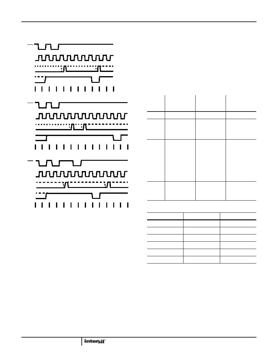
FIGURE 14. MODE 5
SIGNAL
STATUS
MODES
LOW OR
GOING LOW
RISING
HIGH
0
Disables Counting
-
Enables Counting
1
-
1) Initiates
Counting
2) Resets output
after next clock
-
2
1) Disables
counting
2) Sets output
immediately high
Initiates Counting Enables Counting
3
1) Disables
counting
2) Sets output
immediately high
Initiates Counting Enables Counting
4
1) Disables
Counting
-
Enables Counting
5
-
Initiates Counting
-
FIGURE 15. GATE PIN OPERATIONS SUMMARY
MODE
MIN COUNT
MAX COUNT
010
110
220
320
410
510
NOTE: 0 is equivalent to 216 for binary counting and 104 for BCD
counting.
FIGURE 16. MINIMUM AND MAXIMUM INITIAL COUNTS
82C54
发布紧急采购,3分钟左右您将得到回复。
相关PDF资料
IDT2308A-4DCI8
IC CLOCK MULT ZD HI DRV 16-SOIC
IDT2309-1HPGGI
IC CLK BUFFER ZD HI DRV 16-TSSOP
IDT2309A-1HPGG
IC CLK BUFFER ZD HI DRV 16-TSSOP
IDT2309B-1HPGGI
IC CLK BUFFER HIGH DRIVE 16TSSOP
IDT23S05-1HDCGI
IC CLK BUFFER PLL HI DRV 8-SOIC
IDT23S05E-1HDCGI8
IC CLK BUFFER PLL HI DRV 8-SOIC
IDT23S08-1HPGI8
IC CLK MULT PLL HI DRV 16-TSSOP
IDT23S08T-1DC
IC CLK MULT PLL ZD 2.5V 16-SOIC
相关代理商/技术参数
ID82C54/+
制造商:未知厂家 制造商全称:未知厂家 功能描述:Analog Timer Circuit
ID82C54-10
制造商:INTERSIL 制造商全称:Intersil Corporation 功能描述:CMOS Programmable Interval Timer
ID82C54-12
制造商:INTERSIL 制造商全称:Intersil Corporation 功能描述:CMOS Programmable Interval Timer
ID82C55A
功能描述:外围驱动器与原件 - PCI PERIPH PRG-I/O 5V 8MHZ 40CDIP IND RoHS:否 制造商:PLX Technology 工作电源电压: 最大工作温度: 安装风格:SMD/SMT 封装 / 箱体:FCBGA-1156 封装:Tray
ID82C55A/+
制造商:未知厂家 制造商全称:未知厂家 功能描述:Peripheral Interface
ID82C55A-5
制造商:HARRIS 制造商全称:HARRIS 功能描述:CMOS Programmable Peripheral Interface
ID82C59A
功能描述:IC CONTROLLER INTERRUPT 28-DIP RoHS:否 类别:集成电路 (IC) >> 接口 - 控制器 系列:- 标准包装:4,900 系列:- 控制器类型:USB 2.0 控制器 接口:串行 电源电压:3 V ~ 3.6 V 电流 - 电源:135mA 工作温度:0°C ~ 70°C 安装类型:表面贴装 封装/外壳:36-VFQFN 裸露焊盘 供应商设备封装:36-QFN(6x6) 包装:* 其它名称:Q6396337A
ID82C59A
制造商:Intersil Corporation 功能描述:Controller IC Package/Case:28-CDIP